Feed linux for devices [copy] http://www.linuxfordevices.com/rss-feeds-1.xml has loading error: cURL error 22: The requested URL returned error: 404
Feed SparkFun Electronics [copy] http://www.sparkfun.com/feeds/news has loading error: cURL error 22: The requested URL returned error: 405
Feed The RFID Weblog [copy] http://www.rfid-weblog.com/index.rss has loading error: cURL error 22: The requested URL returned error: 404 Not Found
Android Hardware Development Environment

My favorite part of the Android Hardware Development Environment is that I can easily connect to a serial port/ use the USB host capabilities with Android. When I'm done with my project I typically burn my custom image of Android to a microSD card so I can reuse my operating system!
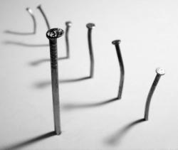
Картина и гвозди

Имеется картина, к которой двумя концами привязана длинная веревка. Требуется повесить её на N вбитых в стену гвоздей так, чтобы при вытаскивании из стены одного любого гвоздя картина и веревка падали.
Веревка имеет пренебрежимо малую толщину, не рвётся и нерастяжима, гвозди не гнутся и перпендикулярны стене, трения нет. Одним словом, задача решается без всяких хитростей и уловок.
Читать дальше →
[Перевод] «Камера» из светодиодов

В этой заметке речь пойдет о том, как массив светодиодов может быть использован в качестве «камеры» очень низкого разрешения (20 пикселей). Практического смысла в этом немного, но опыт применения светодиодов в качестве фотодатчиков может оказаться для кого-то полезным. В работе используется плата Arduino Blinkenlight Shield, изначально предназначенная для демонстрации световых эффектов.
Читать дальше →
Неравномерно идущие часы

Идея этих часов состоит в том, что стрелки на них двигаются неравномерно, то ускоряясь, то отставая, но тем не менее, в среднем, часы показывают правильное время. Сейчас расскажу, как такие сделать.
Читать дальше →
[Перевод] Перехват нажатий клавиш смартфона при помощи акселерометра

Двое исследователей из Калифорнийского университета в Дэвисе (UC Davis), Хао Чэнь (Hao Chen) и Лянь Цай (Lian Cai) нашли способ определять, какие клавиши были нажаты на экранной клавиатуре ОС Android путем измерения смещений, покачиваний и вибрации устройства, измеренных встроенным акселерометром [Прим. перев.: и гироскопом]. Это важно, поскольку данные от акселерометров не рассматривались как потенциальный вектор атаки, и, таким образом, свободно доступны любому приложению на любом смартфоне или планшете.
Читать дальше →
Трансатлантическая линия связи без электричества

Прежде всего, спеша предотвратить гневные возгласы, заявляю: я не знаю решения этой задачи! Точнее так: у меня есть некоторые мысли на этот счет, но красивого и «правильного» решения пока нет. Считайте этот пост возможностью поразмять мозги и почувствовать себя изобретателем.
Итак, условие
Представьте себе цивилизацию, которая достигла нашего нынешнего уровня развития во всем, кроме одного: электричество так и не открыто. Все остальные технологии, не связанные с электричеством, освоены. Физика, химия, металлургия, машиностроение, гидравлика, пневматика, оптика и т.д. — к вашим услугам, а вот даже простейшую батарейку не изобрели.
В таких вот нелегких условиях вам предлагается организовать трансатлантическую линию связи. Естественно, все технологии, так...
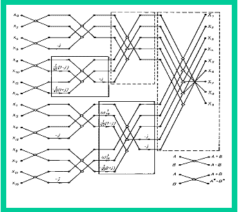
Dataflow-архитектуры. Часть 2

В первой части статьи мы рассмотрели основные отличия архитектуры потока данных (dataflow) от архитектуры потока управления (controlflow), совершили экскурсию в 1970-е, когда появились первые аппаратные dataflow-машины и сравнили статическую и динамическую потоковые модели вычислений. Сегодня я продолжу вас знакомить с dataflow-архитектурами. Добро пожаловать под кат!
Читать дальше →
Dataflow-архитектуры. Часть 1

Вторая часть статьи.
Большинство современных вычислительных машин, будь то суперкомпьютер Fujitsu K, обычная персоналка или даже калькулятор, объединяет общий принцип работы, а именно модель вычислений, основанная на потоке управления (Controlflow). Однако, эта модель не является единственно возможной. В некотором роде ее противоположностью является модель вычислений, управляемая потоком данных, или просто Dataflow. О ней я и хочу сейчас рассказать.
Читать дальше →
Генерация случайных чисел на микроконтроллерах

Про генераторы случайных чисел написано очень много, но почти всегда, когда дело доходит до реализации, подразумевается (или явно говорится), что речь идет об x86/x64 и других «взрослых» архитектурах. В то же время, форумы, посвященные разработке устройств на микроконтроллерах, пестрят вопросами «как мне сгенерировать случайное число на %controllername%?». Причем диапазон ответов простирается от «смотри гугл/википедию» до «используй стандартную функцию». Далеко не всегда эта «стандартная функция» есть и устраивает разработчика по всем параметрам, чаще наоборот: то числа получаются далеки от случайных, то скорость работы слишком мала, а то полученный код вообще не помещается в свободную память.
Попробуем разобраться, какие бывают алгоритмы генерации случайных...
Maker Faire 2011– Bay Area Recap
Each year, I head out to Maker Faire, thinking I’ve seen it all, but I know that can’t be true. And year after year…well, I haven’t been disappointed yet! Besides enjoying some quality time in the gorgeous California sun, we managed to get our project demos up and running for the event.
Here’s the booth, with Will and Francis doing some final setup work on the projects.
Of course, it wouldn’t be Maker Faire without Gerard’s Paella, which also makes for a great excuse to meet and mingle with some fellow makers:
By...
